


استشر الولايات المتحدة
بصفتنا مصنعًا عالميًا رائدًا لمعدات التكسير والطحن ، فإننا نقدم حلولًا متطورة وعقلانية لأي متطلبات لتقليل الحجم ، بما في ذلك إنتاج المحاجر والركام والطحن ومحطة تكسير الحجارة الكاملة. نقوم أيضًا بتوريد الكسارات والمطاحن الفردية وكذلك قطع غيارها.
Crushing Plant Design and Layout Considerations 911
There are three main steps in designing a good crushing plant: process design, equipment selection, and layout The first two are dictated by production requirements and designDownload scientific diagram | Process flow sheet for the crushing tests, including sampling for laboratory testing from publication: Influence of jaw crusher parameters on theProcess flow sheet for the crushing tests, including sampling for
MODELLING, SIMULATION AND OPTIMISATION OF A CRUSHING
process The ultimate objective is to develop a dynamic process simulator, administered in Simulink/MATLAB® background, for application in the design of a control model utilising1999年12月1日· The flow model provides a fundamental understanding of the flow mechanisms occurring in a cone crusher These mechanisms have earlier beenModelling of flow in cone crushers ScienceDirect
A review of modeling and control strategies for cone
2021年8月15日· open access • We review the state of the art developments in process modeling and cone crusher control from 1972 to 2020 • The steadystate model of2015年4月1日· Crusher Breakage Comminution Wear Compression 1 Introduction Crushers are typically the first stage of comminution processing for run of mine ore inSimulation of particle flows and breakage in crushers
Crusher an overview | ScienceDirect Topics
Schematic diagram showing principle of jaw crusher showing the path of lumpy feed ore to fragmented product crushed under high pressure of fixed and moving jaws The type ofSchematic description of the crushing plant, (1) primary crusher, (2) secondary crusher, (3) tertiary crushers, (4) final screens and (5) a switch for changing the process flow SourceSchematic description of the crushing plant, (1) primary crusher, (2
The flowchart of crushing process with onestage and threestage
The flowchart of crushing process with onestage and threestage reduction Source publication +1 Effects of Two Important Parameters on Capacity of a Laboratory Jaw2022年11月12日· This process is pretty linear and a great example of how you can visualize a subsequent order of tasks: Step 1: Request your paid time off (PTO) Step 2: Your manager reviews your request Step 3: Your manager decides whether or not they will approve your request Step 4: You’ll receive an about your manager’s decisionWhat is Process Flow and How Can You Visualize it? [2023] • Asana
Development of an automatic can crusher using ResearchGate
1796 ISSN: 20888708 Int J Elec & Comp Eng, Vol 9, No 3, June 2019 : 1794 1804 with the tremendous amount of empty leftover beverageA Process Flow Diagram (PFD) is a type of flowchart that illustrates the relationships between major components at an industrial plant It's most often used in chemical engineering and process engineering, though its concepts are sometimes applied to other processes as well It’s used to document a process, improve a process or model a newWhat is a Process Flow Diagram | Lucidchart
Simulation and Optimization of an Integrated Process Flow Sheet
2021年3月9日· In this study the process flow diagram for the cement production was simulated using Aspen HYSYS 88 software to achieve high energy optimization and optimum cement flow rate by varying the flow rate of calcium oxide and silica in the clinker feed Central composite Design (CCD) of Response Surface Methodology was used toRoll Crushers A Gupta, DS Yan, in Mineral Processing Design and Operation, 2006 613 Roll Crusher Circuit Design Roll crushers are generally not used as primary crushers for hard ores Even for softer ores, like chalcocite and chalcopyrite they have been used as secondary crushers Choke feeding is not advisable as it tends to produce particles ofCrusher an overview | ScienceDirect Topics
Figure 1 Process flow diagram of Stamicarbon’s original
Process description The process flow diagram of the original Stamicarbon granulation design is shown in figure 1 The urea melt, with a concentration of about 985% wt is transferred to the granulator, the core of the process, in which it is distributed by a number of film spraying nozzles As the granules move along through2 Process Flow Diagram In general, the following information is shown on a PFD • Process piping above a certain size, such as 2 inches • Process flow directions • Major equipment • Bypass and circulation lines • Control valves and processcritical block valves • Connections between systems located on other PFDsINTRODUCTION TO MINERAL PROCESSING FLOWSHEET DESIGN
26 Effluent Treatment Plant Process Flow Diagram
2021年1月16日· Effluent treatment plant process flow diagramEffluent treatment block is that part of industry which never take part in production but help to treat the affluent The main role of ETP is purify the effluent which is come from production plant Effluent is that part of production which is not a product , which is west , which need to purifyFigure 1 is a process flow diagram of the circuit that indicates the arrangement of the various controlled, manipulated and measured disturbance variables used in the MPC controller This paperProcess flow diagram of the primary ROM ball milling circuit
Process Flow Diagram Symbols | Mechanical Drawing Symbols
Chemical and Process Engineering solution contains variety predesigned process flow diagram elements relating to instrumentation, containers, piping and distribution necessary for chemical engineering, and can be used to map out chemical processes or easy creating various Chemical and Process Flow Diagrams in ConceptDraw DIAGRAM OilTo document a process flow, start by identifying the specific process you want to chart or diagram and break it down into a series of steps Make a visual representation of these steps through a flowchart Use differentFree Process Flow Diagram Maker and Examples
Schematic description of the crushing plant, (1)
Download scientific diagram | Schematic description of the crushing plant, (1) primary crusher, (2) secondary crusher, (3) tertiary crushers, (4) final screens and (5) a switch for changing the2022年8月4日· In the first stage, 15% cement, 10% water, 25% sand and 50% small stones are mixed in a concrete mixer machine and the machine rotates fast to have the ingredients mixed together to create theGraph Writing # 102 Stages and equipment used in
Cement Production Process | PPT SlideShare
2015年9月17日· 600 Limestone Quarry and Crushing plant The major raw material for cement production is limestone The limestone most suitable for cement production must have some ingredients in specified quantities ie, calcium carbonates, silica, alumina, iron,etc Belt Conveyors The quarried raw material is transported to the cement plant,A process flow diagram for construction sand and gravel processing is presented in Figure 111911 or it may be directed to a crusher for size reduction, to produce crushed aggregate, or to produce manufactured sands Crushing generally is carried out in one or two stages, although threestage crushing may also be performed11191 Sand And Gravel Processing US EPA
(PDF) Research on Structural Design of Coal Crusher House in
2020年7月24日· This paper takes the specific characteristics of pulverized coal room in thermal power plant as the starting point,firstly, this paper analyzes the process layout and structure selection, andProcess Flow Diagrams or PFDs are developed using a series of symbols and notations to convey information for a process The concept of PFD or process flow diagram was first introduced to ASME by Frank Gilbreth, Sr in the year 1921 Purpose of PFD or Process Flow Diagram The purpose of the process flow diagram is to define the design of theWhat is Process Flow Diagram (PFD)? Purpose, Symbols, Examples
Manufacture Of Portland Cement | Process | Flow chart civil
2019年11月30日· Mixing of raw materials: The processes used for the manufacture of portland cement can be classified as dry and wet In dry process The raw materials are first reduced in size of about 25mm in crushers and Crushed material is ground to get fine particles into ball mill or tube mill Each material after screening is stored in a separate39 Item Part No Image 1 DE1007 2 DE6000 3 DE6004 4 DE6015 5 DE6006 DE5024 6 DE6007 7 DE0027 tagout)QH441OperationManual Crusher Works
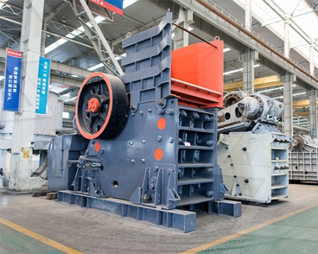
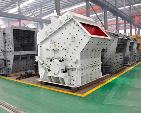
Manufacturing Process/Flow Chart of Stone Crusher Plant
2019年9月16日· Manufacturing Process/Flow Chart of Stone Crusher Plant 1 The Stone Crusher Plant is used for the production of raw materials of aggregates like 40 mm 20mm , 10mm, 6 mm , Dust, GSB & Crushed Sand 2 The Stone Crusher is available in three variants like, Primary Crusher or Jaw Crusher, Secondary Crusher or Cone